GitHub repo here: GitHub
Overview
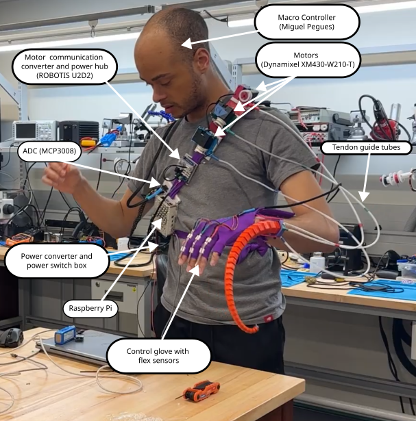
Polydact is a wearable robotic sixth finger that gives its user greater dexterity than they have with their natural hand. The Polydact device is controlled by a hand made glove with embedded flex sensors.
Click here for more detailed videos...
Part/person assembly...
Initialization and calibration...
Full recording (9:42) with annotations...
Full recording without annotations...

Tentacle Design
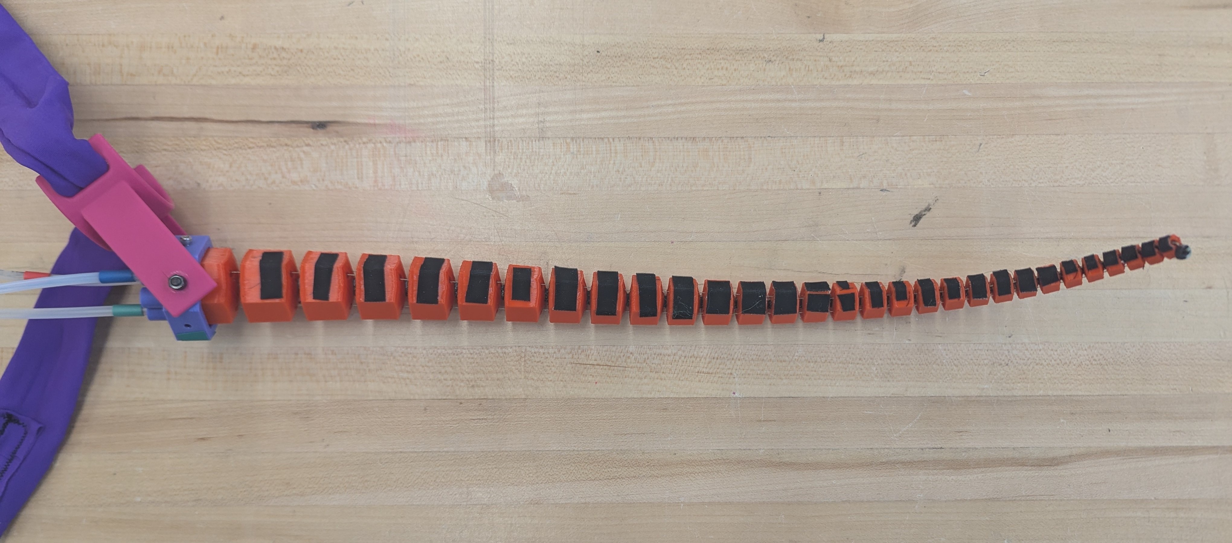
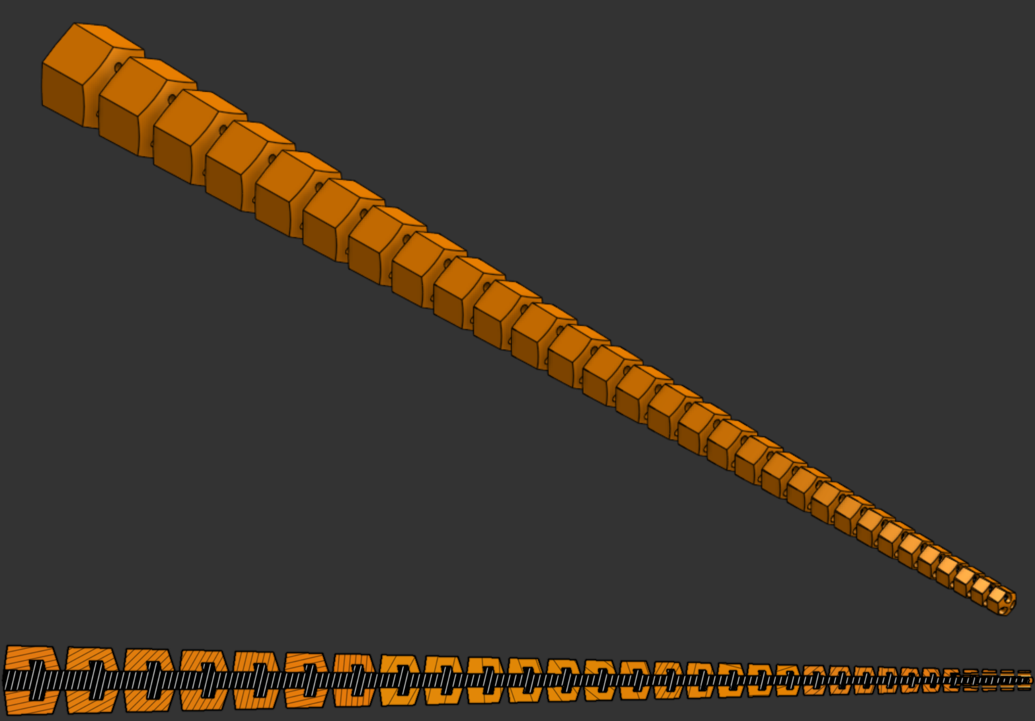
The design of the tentacle is based on logarithmic spirals, as developed by Z. Wang (Reference 1). It was 3D printed in one piece with PLA bones (orange) on a TPU spine (black, only visible in section image). The interior barbs along the spine are added to guarantee that the bones cannot slide off of the spine even if the TPU and PLA lose adhesion. 3M GM640 gripping tape (black) is added to the main inner surface both for the added grip and also to indicate the main coiling direction.
Click here for further design detail...
Scaling factors a and b were set as 1.0 and 0.1 respectively, with a split angle of 30°. I wanted the tentacle to be able to coil around itself twice when fully tightened in one direction, so I required at least 24 bones and used 30. With a = 1.0 and b = 0.1, the tightest coil possible is ~2.3 cm. 2.3 cm, just over an inch, is the smallest diameter object I can pick up. I did not have a specific target for largest diameter.See Reference 1 for spiral math derivations.
Control
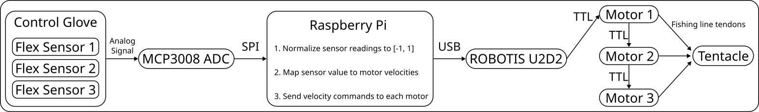
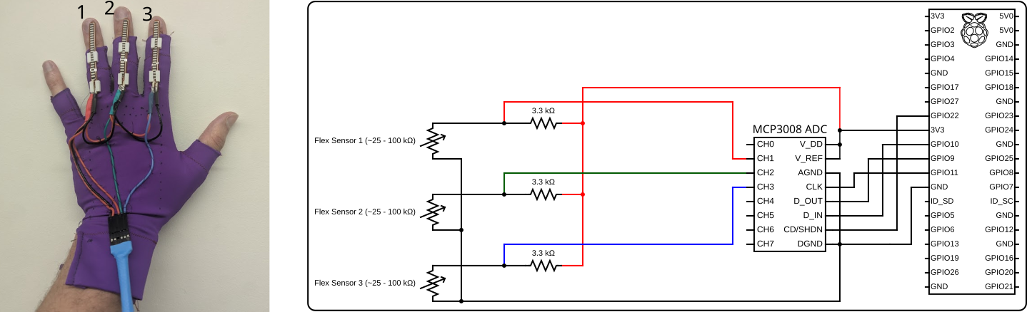
Polydact’s main control device is a glove with integrated flex sensors. The flex reading is mapped to motor velocity, which spool or unspool the three cables that travel the entire length of the tentacle and terminate in a knot at its free end. Several parts on the entire Polydact device are color coded red, green, and blue. This makes it easier for the user to know which finger controls which direction of tentacle coiling.
By default, ring finger flexion causes the tentacle to coil towards the wrist on the back of the hand (color coded red), middle finger flexion causes the tentacle to coil towards the elbow in the plane of the palm (color coded green), and index finger flexion causes the tentacle to coil towards the wrist on the front of the hand (color coded blue). The index finger coil direction is the easiest to use for grasping objects.
Part Mounting
- Tentacle screws to socket (purple)
- Socket screws to wrist mount (pink)
- Wrist mount ties to user with spandex band
- All other parts attach to chest band
Further detail...
The tentacle itself is seated in a hexagonal socket (purple) that has receptacles on the back to hold the tendon guide tubes in place and holes in the center of each face. Screws in these holes hold the tentacle in place and also attach the socket to the wrist mount (pink). The angle of the socket in the plane of the hand is easily adjusted by tilting it in the wrist mount before tighening the nuts on the outside of the wrist mount.
The wrist mount has slots for a strap; it is tied to the user with a band of spandex. Most other parts (the switch box, Raspberry Pi, Robotis U2D2, and motor strap) are also attached to the user with a larger band across the chest. The motors are held in frames with dovetail connectors that slide into the motor strap. The battery is placed in the user's pocket.
I sewed the control glove using the same spandex as the wrist and chest bands. Flex sensors are held in 3D printed slots sewn into the back of the middle three fingers. Sensor wiring is also sewn onto the back of the glove.
The tentacle, socket, wrist mount, motor strap, motor frames, spools, and sensor slots were 3D printed. The Raspberry Pi case and U2D2 mount are made of a combination of 3D printed and laser cut parts, although they were designed to all be easily laser cut. The switch box is intentionally a combination of 3D printed and laser cut parts. I designed all 3D printed and laser cut parts.
Click here to see a few CAD models...
ROS Nodes
Two nodes must be run to control the device: a sensor node (serial or Pi/ADC) and a motor coordinator node. The sensor node reads flex values and publishes MotorGoal messages to command motor velocity. The motor coordinator node subscribes to the MotorGoal messages and uses the DynamixelSDK to write commands to the motors.
During early development, flex values were read using a Raspberry Pi Pico 2’s ADC pins and sent over USB serial to my laptop, which was running both the serial sensor and motor coordinator nodes. Flex values are currently read using a MCP3008 ADC connected to a Raspberry Pi running its own sensor node. The motor coordinator can run on either the Raspberry Pi or a laptop connected to the same network.
Thanks
Polydact would look much different without conversations, advice, and assistance from the following people. They all have my gratitude and thanks.
- Day Lekberg, for sewing lessons
- Greg Aiosa (also MSR ‘26), for discussions on materials and general 3D printing expertise
- Joshua Lantz, for sewing assistance
- Nolan Knight (also MSR ‘26), for mechatronics discussions
- Raphael Cherney for general help with fabricating many parts
References
[1] Z. Wang, “SpiRobs: Logarithmic spiral-shaped robots for versatile grasping across scales,” Device, vol. 3, April 2024, doi:10.1016/j.device.2024.100646